
- Тип техники
- Бренд
Просмотр инструкции материнской платы Gigabyte 8S661FXM RZ, страница 16
- 16 -
8S661FXM-RZ Motherboard
English
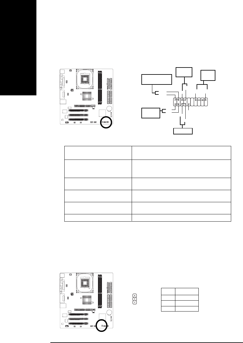
7) F_PANEL (2x10 pins connector)
Please connect the power LED, PC peaker, reset switch and power switch etc of your chassis front
panel to the F_PANEL connector according to the pin assignment above.
HD (IDE Hard Disk Active LED) Pin 1: LED anode(+)
Pin 2: LED cathode(-)
SPK (Speaker Connector) Pin 1: VCC(+)
Pin 2- Pin 3: NC
Pin 4: Data(-)
RST (Reset Switch) Open: Normal Operation
Close: Reset Hardware System
PW (Soft Power Connector) Open: Normal Operation
Close: Power On/Off
MPD(Message LED/Power/ Pin 1: LED anode(+)
Sleep LED) Pin 2: LED cathode(-)
NC NC
SPK-
SPK+
20
Speaker
Connector
1
19
IDE Hard Disk
Active LED
Reset Switch
2
1
Soft Power
Connector
1
MPD+
MPD-
Message LED/Power/
Sleep LED
PW-
PW+
1
HD+
HD-
1
RST+
RST-
NC
1
8 ) PWR_LED
PWR_LED is connect with the system power indicator to indicate whether the system is on/off. It will
blink when the system enters suspend mode. If you use dual color LED, power LED will turn to
another color.
Pin No. Definition
1 MPD+
2 MPD-
3 MPD-
1
Ваш отзыв будет первым