
- Тип техники
- Бренд
Просмотр инструкции материнской платы Gigabyte GA MA790FXT UD5P, страница 29
Hardware Installation- 29 -
11) PWR_LED (System Power LED Header)
This header can be used to connect a system power LED on the chassis to indicate system power
status. The LED is on when the system is operating. The LED keeps blinking when the system is
in S1 sleep state. The LED is off when the system is in S3/S4 sleep state or powered off (S5).
Pin No. Definition
1 MPD+
2 MPD-
3 MPD-
System Status LE D
S0 On
S1 Blinking
S3/S4/S5 Off
1
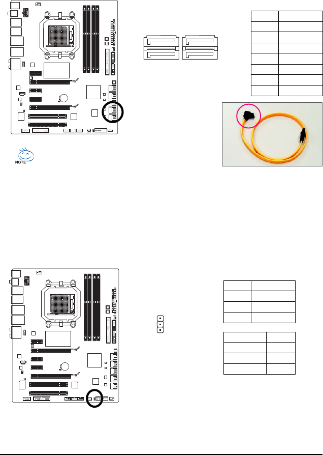
10) GSAT A2_0/1/2/3 (SAT A 3Gb/s Connectors, Controlled by GIGABYTE SA TA2/JMB322, White)
The SATA connectors conform to SATA 3Gb/s standard and are compatible with SATA 1.5Gb/s
standard. Each SATA connector supports a single SATA device. The GIGABYTE SATA2/JMB322
controller supports RAID 0, RAID 1 and JBOD. Refer to Chapter 2, "Integrated Peripherals" and
Chapter 5, "Configuring SATA Hard Drive(s)," for instructions on configuring a RAID array.
Pin No. Definition
1 GND
2 TXP
3 TXN
4 GND
5 RXN
6 RXP
7 GND
A RAID 0 or RAID 1 configuration requires two hard
drives. The two hard drives must be connected to either
the GS ATA2_0 and G SATA2_1 connectors as an array
or to the GSATA2_2 and G SATA2_3 connectors.
Please connect the L-shaped end of the
SATA 3Gb/s cable to your SA T A hard drive.
GSATA2_0
GSATA2_1
GSATA2_2
GSATA2_3
1
1
7
7
Ваш отзыв будет первым