
- Тип техники
- Бренд
Просмотр инструкции материнской платы Gigabyte GA P55 UD5 rev 1 0, страница 23
- 23 - Hardware Installation
1-9 Onboard LEDs and Buttons
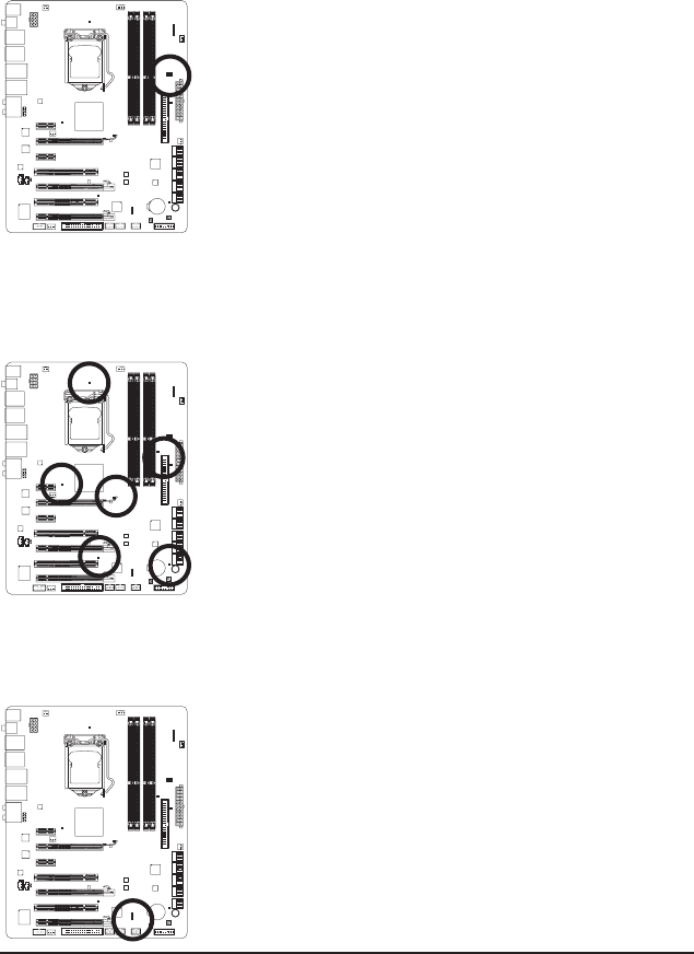
Diagnostic LEDs
This motherboard has 7 onboard LEDs controlled by the system BIOS. The 7 LEDs indicate if a component
(including CPU and memory) or a device (including PCI and PCIe cards and IDE/SATA devices) works abnor-
mally. The LEDs will light up during the POST when the components/devices have a problem.
CPU: CPU_LED
Memory: DIMM_LED
IDE: IDE_LED
SATA: SA_LED
PCIe x16/x8: PE_LED
PCIe x4/x1: PE1_LED
PCI: PCI_LED
ACPI LEDs
The 4 embedded ACPI LEDs indicate the system power status (S0, S1, S3, S4, S5) to prevent potential hard-
ware damage due to improper plug/unplug actions.
ACPI LEDs:
S0_LED
S1_LED
S3_LED
S4_S5_LED
CPU VTT/Memory Phase Indicator LEDs
This motherboard contains 4 phase indicator LEDs controlled by the system BIOS to indicate the phase sta-
tus of the CPU VTT and memory. The green LEDs light up under normal working conditions; the yellow LEDs
will be illuminated when an excessive overvoltage or overloading occurs.
CPU VTT:
GD1: Normal working conditions (green LED)
GD2: Excessive overvoltage or overloading (yellow LED)
Memory:
MD1: Normal working conditions (green LED)
MD2: Excessive overvoltage or overloading (yellow LED)
Ваш отзыв будет первым