
- Тип техники
- Бренд
Просмотр инструкции материнской платы Gigabyte GA 8IPE1000 Pro2 W, страница 30
- 26 -GA-8IPE1000 Series Motherboard
English
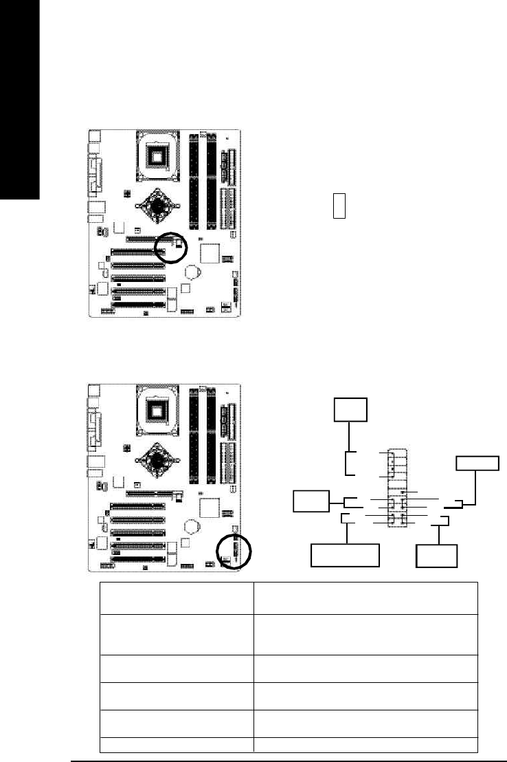
12) F_PANEL (2x10 pins connector)
Please connect the power LED, PC peaker, reset switch and power switch etc of your chassis front panel
to the F_PANEL connector according to the pin assignment above.
HD (IDE Hard Disk Active LED) Pin 1: LED anode(+)
(Blue) Pin 2: LED cathode(-)
SPEAK (Speaker Connector) Pin 1: VCC(+)
(Amber) Pin 2- Pin 3: NC
Pin 4: Data(-)
RES (Reset Switch) Open: Normal Operation
(Green) Close: Reset Hardware System
PW (Soft Power Connector) Open: Normal Operation
(Red) Close: Power On/Off
MSG(Message LED/Power/ Pin 1: LED anode(+)
Sleep LED)(Yellow) Pin 2: LED cathode(-)
NC( Purple) NC
11) 2X_DET
When an AGP 2X (3.3V) card is installed the 2X_DET will light up, indicating a nonsupported graphics
card is inserted. Informing users that system might not boot up normally due to AGP 2X (3.3V) is not
supported by the chipset.
+
-
SPEAK-
SPEAK+
20
Speaker
Connector
1
19
IDE Hard Disk
Active LED
Reset Switch
2
1
Soft Power
Connector
1MSG+
MSG-
Message LED / Po w e r /
Sleep LED
PW-
PW+
1
HD+
HD-
1 RES+
RES-
NC
1
Ваш отзыв будет первым