
- Тип техники
- Бренд
Просмотр инструкции материнской платы Gigabyte GA 8ILMT4, страница 24
- 21 - Hardware Installation Process
English
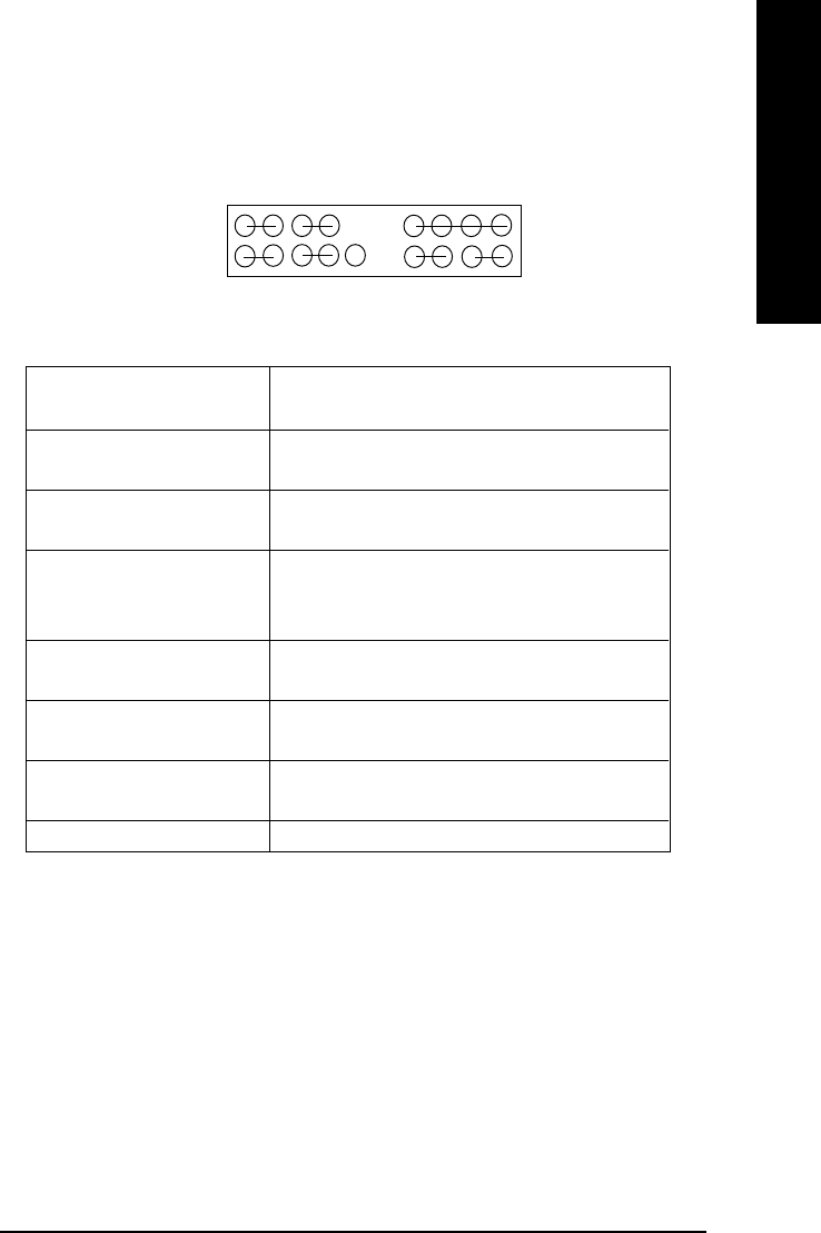
J) F_PANEL (2x10 pins connector)
$ Please connect the power LED, PC speaker, reset switch and power switch etc of your chassis
front panel to the F_PANEL connector according to the pin assignment above.
GN (Green Switch) Open: Normal Operation
Close: Entering Green Mode
GD (Green LED) Pin 1: LED anode(+)
Pin 2: LED cathode(-)
HD (IDE Hard Disk Active LED) Pin 1: LED anode(+)
Pin 2: LED cathode(-)
SPK (Speaker Connector) Pin 1: VCC(+)
Pin 2- Pin 3: NC
Pin 4: Data(-)
RE (Reset Switch) Open: Normal Operation
Close: Reset Hardware System
PW (Soft Power Connector) Open: Normal Operation
Close: Power On/Off
MPD(Message LED/Power/ Pin 1: LED anode(+)
Sleep LED) Pin 2: LED cathode(-)
NC NC
HD+
MPD+
2
20
1
19
GD-
PW-
PW+
RST-
SPK+
SPK-
1
RST+
HD-
GD+
1
MPD-
GN-
GN+
NC
1
1
1
1
1
Ваш отзыв будет первым