
- Тип техники
- Бренд
Просмотр инструкции материнской платы Gigabyte GA 8IE800, страница 24
- 20 -GA-8IE800 Motherboard
English
1
HD+
SPK-
19
HD-
SPK+
202
1
1
Speaker
Connector
Soft Power
Connector
1
1
1
MPD+
MPD-
Message LED/Power/
Sleep LED
PW-
PW+
IDE Hard Disk
Active LED
RSE+
RSE-
Reset Switch
NC
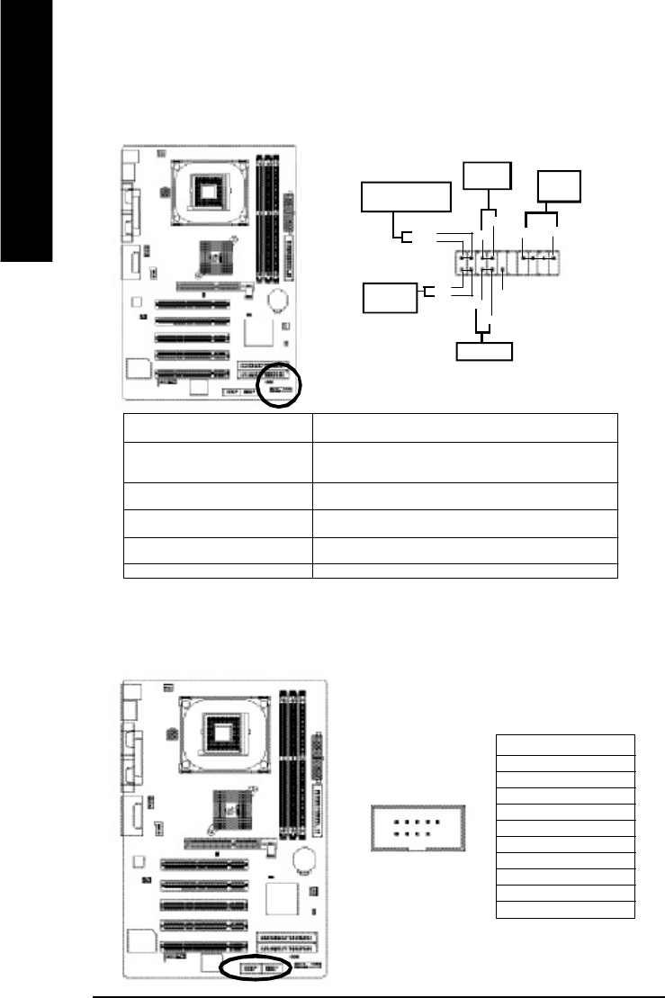
9) F_PANEL (2x10 pins connector)
Please connect the power LED, PC peaker, reset switch and power switch etc of your
chassis front panel to the F_PANEL connector according to the pin assignment above.
HD (IDE Hard Disk Active LED) Pin 1: LED anode(+)
(Blue) Pin 2: LED cathode(-)
SPK (Speaker Connector) Pin 1: VCC(+)
(Amber) Pin 2- Pin 3: NC
Pin 4: Data(-)
RES (Reset Switch) Open: Normal Operation
(Green) Close: Reset Hardware System
PW (Soft Power Connector) Open: Normal Operation
(Red) Close: Pow er On/Off
MSG(Message LED/Power/ Pin 1: LED anode(+)
Sleep LED)(Yellow) Pin 2: LED cathode(-)
NC( Purple) NC
10)F_ USB1 / F_USB2(Front USB Connector, Yellow )
Be careful with the polarity of the front USB connector. Check the pin assignment while you
connect the front USB cable. Please contact your nearest dealer for optional front USB cable.
1
Pin No. Definition
1 Power
2 Power
3 USB DX-
4 USB Dy-
5 USB DX+
6 USB Dy+
7 GND
8 GND
9 No Pin
10 NC
2
9
10
Ваш отзыв будет первым