
- Тип техники
- Бренд
Просмотр инструкции сварочного оборудования Awelco BLUEMIG 130, страница 8
3.2. WIRE-FEEDER MOTOR
M ak e sur e th at t he s ize of the gr oove in t h e feed r oll c orr esp on ds t o t h e
welding wire size being used. The feed roll has the wire diameter
st amp ed on its s id e. Th e m ac h in es are eq u ipp ed w ith pr oper s h agren eed
rolls suitable for welding with flux cored wire without gas protection. To
weld w ith fu ll w ir e wit h GAS pr ot ect ion y ou have to r eplac e th e roll of th e
wir e feeder gr oup w hic h has V for m f or the s t eel wir e an d U form for the
aluminium wire. If you intend to use the welder with gas protection you
hav e t o r equ ir e s uch r olls and the pr ess ur e reduc er to your retai ler or t o
t he bui ld er s oci e ty.
3.3. FEEDING WIRE INTO THE WELDING TORCH
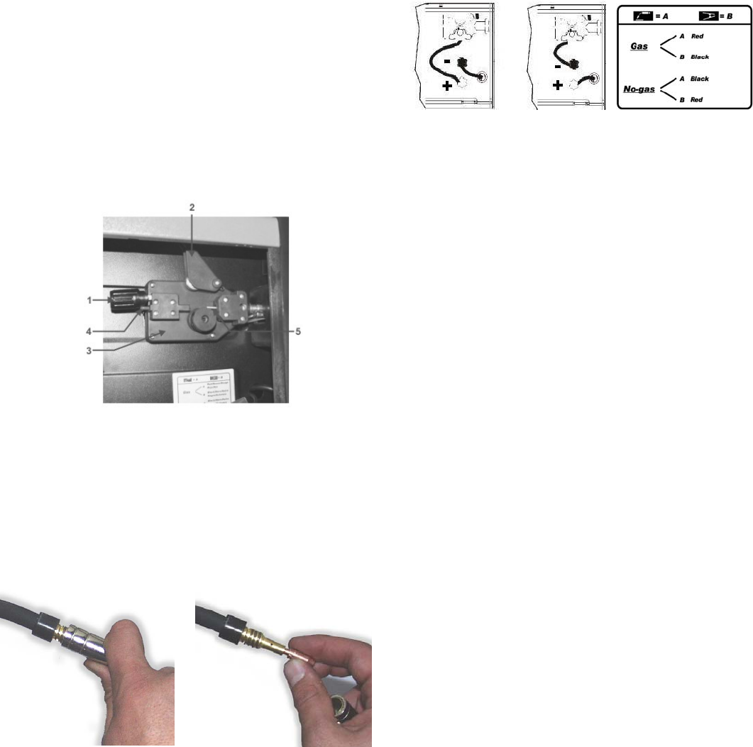
1. Release the Spr ing Loaded Press ure Arm (1) rotate the Idle Roll Ar m
(2) away from the W ire Feed Drive Roll (3). Ensur e that the gr oove siz e
in the f eeding p osition on t he drive roll matches the wire size being used.
2. Carefully detach the end of the wire from the spool. To prevent the
spool from unwinding, maintain tension on the wir e until after step 5.
3. Cut t he bent portion of wir e off an d straighten the first 10 cm .
4. Thr ead t he wir e thr oug h t he ing oing gu ide t ub e (4), ov er t he driv e rol l
(3), and into the outgoing gui de tube ( 5).
5. C los e the id le rol l arm and lat ch th e spr ing load ed pr ess ure a rm ( 2) in
place. Rotate the spool counterclockwise if required to take up extra
slack in the wire.
6. The idle roll pressure adjustment wing nut is normally set for mid-
pos ition on th e press ur e arm thr eads . If f eeding pr obl ems occ ur b ec aus e
the wire is flattened excessively, turn the pressure adjustment counter-
clockwis e to reduc e dist ortion of the wir e. Slightly less press ure may b e
required when using 0,6 mm w ire. If th e dri ve roll slips whi le feeding wire,
th e pr essure sh oul d b e increas ed until t h e wir e f eed s pr op er ly.
7. Rem ov e g as n oz zl e and c ont act t i p from end of g un.
8. Turn the machine ON (“I”).
9. Straighten the gun cable assembly.
10. Depress the gun trigger sw itch and feed w elding wire through the gun
and c ab le. (P oint gun away f rom yours elf and ot hers whil e f eedi ng wir e.)
Release gun trigger after wire appears at end of gun.
11. Turn the machi ne OFF (“O”) .
12. R ep l ac e c ont act t ip and g as n ozz l e.
13. Cut the wire off 6 – 10 mm from the end of the tip. The machine is
now ready to weld.
3.4. TORCH CONNECTION
The t orc h is connected direct ly to the welding machine so it is ready for
use. A pr obable r eplacement of the torch must be done with care and if
possible by a technician. To replace contact tips, it is necessary to
unscr ew or to pull it. Replace tip, check that it corr esponds with the wir e
size and replace the gas shroud. For good wire feeding during welding
operations, it is essential that the correct size parts are used for each
wire. Keep always clean the contact t ip.
4. WELDING MODE
4.1. CONTINUOUS WELDING
It is th e m od e in w h ich t h e w eld i ng m ac h in e is likely to be used t h e m ost .
In this mode, you have only to press the button of the torch and the
welding machine begins to work. To stop welding it is necessary
releasing the torch button.
4.2. GAS PRESSURE
Gas pressure should normally be set to give a reading between 6 / 12
litres per minute on the flowmeter. Anyway, every oper ator will find what
suits him the most with his type of work and can make the necessary
adj us tm ent .
4.3. GAS – NO GAS WEL DING MOD E
4.3.1. Ga s - Connect torch cl am p to positive terminal “+” and earth clamp
to negative(-)
4.3. 2. N o ga s - ( only f or pr es et m od els) C onn ect eart h clam p t o pos it iv e
terminal (+) and the torch clamp to n egative (-).
4.4. MIG - MAG WELDING MODE
A ) MIG = Metal Inert Gas
B ) MAG = Metal Active Gas
Thes e two modes ar e perf ectly equival ent, the diff erenc e is given by the
kin d of gas y ou us e. In c as e A the gas empl oyed is A RG ON ( in ert gas).
In case B the gas employed is CO
2
( active gas). To weld alluminium
alloys you need use ARGON (100%), to weld steel it is enough a
compound of ARGON 80% and CO
2
20%. You c an on ly use CO
2
in case
you w il l wel d iron.
5. WELDING GUIDE
5.1. GENERAL RULE
When welding on the lowest output settings, it is necessary to keep the
arc as short as possible. This should be achieved by holding welding
torch as close as possible and at an angle of approximately 60 degrees
to the work piece. The arc lengt h can be incr eased when welding on the
highest settings, an arc length up to 20 mm can be enough when welding
on maximum settings.
5.2. GENERAL WELDING TIPS
From time to time, some faults may be observed in the weld owing to
external influences rather due to welding machine’s faults. Here are
some that you may come across :
· Porosity
Small holes in the weld, caused by break-down in gas coverage of the
weld or sometimes by foreign bodies inclusion. Remedy is, usually, to
grind out the weld. Remember, check before the gas flux (about 8
liters/minutes), clean well the working place and finally incline the torch
while welding.
· Spatter
Small balls of molten metal which come out of the arc. A little quant ity is
unavoidable, but it should be kept down to a minimum by selecting
correct settings and having a cor rect gas fl ow and by keep ing the welding
torch clean.
· Narrow heap welding
C an be caused by moving the torch too fast or by an incorrec t gas f low.
· Very t hick or wide welding
C an be caused by moving the torch too sl owly.
· W ire b urns back
It can be caused by wire feed slipping, loose or damaged welding tip,
poor wire, nozzle held too c lose to work or voltage too high.
· Little penetration
It can be caused by moving torch too fast, too low voltage setting or
inc orr ect f eed s ett ing, r ever sed p olar ity, ins uffic ient blunt ing an d dis tance
between strips. Take care of operational parameters adjustment and
improv e the prep ar ation of t he w orkp iec es.
· Workpiece’s piercing
It m ay be caused by m ov i ng t h e wel d ing tor ch t oo sl ow, too hi gh w eld i ng
pow er or by an inv al id w ir e f eed i ng.
· Heavy spatter and porosity
It c an be caus ed by nozzle t oo f ar f rom work, dirt on work or b y l ow gas
flow. You have to the two parameters, remeber that gas has not to be
lower than 7-8 liters/ min. and that the curr ent of welding is appropr iated
to the wire you are using. It is advisable to have a pressure reducer of
input and output. On the m anom eter you c an read the range express ed
in liter.
· Welding arc insta b ility
It may be caused by an insufficient welding voltage, irregular wire feed,
insuffici ent protecti ve welding gas.
Ваш отзыв будет первым