- Тип техники
- Бренд
Просмотр инструкции снегоходы Ski Doo SUMMIT 2005, страница 692


Section05ELECTRICALSYSTEM
Subsection 03 (STARTING SYSTEM)
If the solenoid does not receive a signal and the
start switch test good, make sure it is not a bad
connection between the engine control module
(ECM) and the starting solenoid. If not, the ECM
can be suspected.
If the solenoid receives current, test it as follows.
– Disconnect battery and starter cables from so-
lenoid.
– Inspect connections and clean as necessary.
– Solenoid condition can be checked with an
ohmmeter. Install probes on large connectors
of solenoid.
– Measure the resistance when current is applied
to small connectors; if it is more than a few
ohms, replace solenoid.
If solenoid tests good, check the electric starter.
Engine Control Module (ECM)
NOTE: When testing the start switch with
B.U.D.S., the starting solenoid signal from the
ECM is also confirmed. If the test is conclusive,
the ECM is in good condition.
Check if there are any fault codes. Refer to EN-
GINE MANAGEMENT.
Engine Cut-Out Switch
Check the condition of engine cut-out switch as
per following table.
ENGINE CUT-OUT SWITCH
TEST
Running
insulation
Continuity in
STOP position
TEST
PROBES
BLACK/YELLOW
and BLACK
wires
BLACK/YELLOW
and BLACK
wires
RESISTANCE
O.L.
00.0 to 00.5
VOLTAGE
— —
NOTE
Engine cut-out
switch must be
in run position.
Engine cut-out
switch must be
in stop position.
Electrical Cables and Connections
Check all connections, harnesses and wires.
Tighten any loose connections.
Replace any chafed wires.
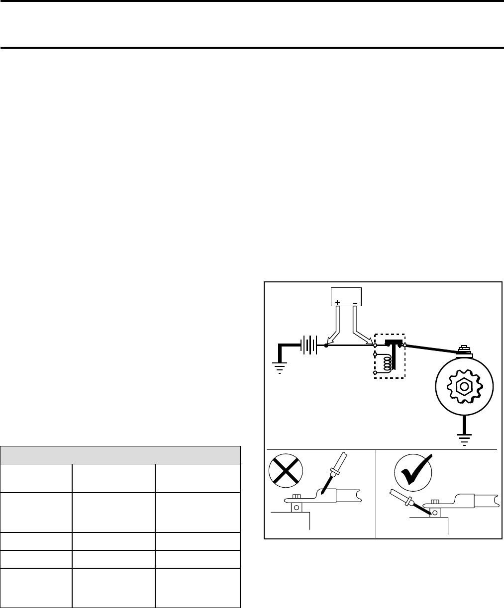
A voltage drop test can be performed in order to
find a poor connection, defective wire or compo-
nent, causing parasite resistance in the system.
To perform a voltage drop test, proceed as follows:
CAUTION: Do not active starter more than
15 seconds. Wait 2 minutes between each
test.
NOTE: Place probes to terminals not to the con-
nectors. More that one component can be defec-
tive. Repair any defective component before per-
forming the next test.
TEST 1
– Place the positive probe of multimeter on posi-
tive battery terminal and the negative probe on
the high-current input of starter solenoid.
Volt
A35E06A
– Crank engine and record the result.
– The voltage reading should not exceed 0.2 volt.
If the result is over 0.2 volt, verify connections
and wire condition.
TEST 2
– Check solenoid by placing the test probes to the
solenoid terminals.
172 mmr2005-129
Ваш отзыв будет первым


