
- Тип техники
- Бренд
Просмотр инструкции снегоходы Ski Doo SUMMIT 2005, страница 666
Section 04 ENGINE MANAGEMENT (SDI)
Subsection 03 (COMPONENT INSPECTION, REPLACEMENT AND ADJUSTMENT)
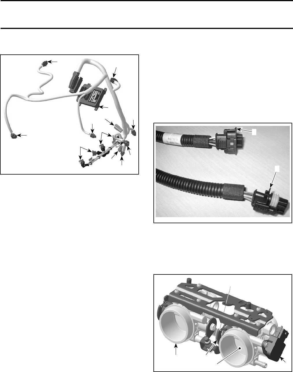
ENGINE WIRING HARNESS
A35C41A
5
10
9
1
2
8
3
7
11
12
6
4
1. ECM
2. CTS connector
3. EGTS connector (NOT USED)
4. Fuel injector connector (cylinder MAG side)
5. Ignition coil connector
6. Fuel injector connector (cylinder PTO side)
7. TPS connector
8. ATS connector
9. Engine/vehicle connector
10. APS connector
11.KS connector
12. CPS connector
Resistance Test
Check continuity of the circuits according to the
wiring diagram in the WIRING DIAGRAMS section
of this manual.
If wiring harness is good, check the respective
sensor/actuator as described in this section.
Otherwise, repair the connectors, replace the
wiring harness or the ECM as diagnosed.
Removal
Remove air intake silencer.
Disconnect the wiring harness from all sensors/
actuators.
Disconnect the connector from the ECM.
Cut all locking tie which are holding the wiring har-
ness in position.
Remove complete wiring harness.
Installation
First connect the connector A to the ECM and the
engine/vehicle connector to the vehicle wiring har-
ness.
Reconnect the wiring harness to all sensors/
actuators and reinstall all locking tie that have
been removed.
NOTE: Pay attention not to mix the ignition coil
connector and the APS connector. Refer to the
illustration below for visual difference.
A35C42A
1
2
1. Ignition coil connector — open housing
2. APS connector — closed housing
Install all remaining parts, which have been re-
moved.
THROTTLE BODY
A35C3VA
1
4
3
2
1. Throttle body
2. Throttle cable attachment
3. Throttle plate
4. TPS
mmr2005-126 145
Ваш отзыв будет первым