
- Тип техники
- Бренд
Просмотр инструкции снегоходы Ski Doo SUMMIT 2005, страница 660
Section 04 ENGINE MANAGEMENT (SDI)
Subsection 03 (COMPONENT INSPECTION, REPLACEMENT AND ADJUSTMENT)
A35C3UA
CAUTION: If not using the ECM adapter, probe
on top of terminal only. Do not try to probe in-
side terminal or to use a paper clip to probe in-
side terminal, it will damage the square-shaped
terminal and this could lead to improper func-
tion of the engine management system.
A32CCPA
PROBE ONLY TOP OF TERMINAL
Use this diagram to locate the pin numbers on
the ECM connector of the wiring harness when
performing tests.
R1503motr176A
1
13
28
41
29
14
TERMINAL IDENTIFICATION OF ECM CONNECTOR
(WIRING HARNESS SIDE)
CAUTION: Do not disconnect the ECM connec-
tor needlessly. They are not designed to be dis-
connected/reconnected repeatedly.
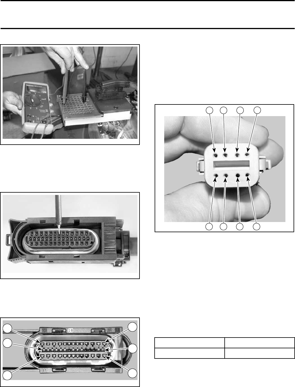
Engine/Vehicle Connector
Use this illustration to locate the terminal numbers
on the engine/vehicle connector of the wiring har-
ness when performing tests.
6
A32C9IA
7
8
5
1
2
34
TERMINAL IDENTIFICATION OF ENGINE/VEHICLE
CONNECTOR (WIRING HARNESS SIDE)
Relay 2
Connect vehicle communication kit (VCK) and use
B.U.D.S. software.
Energize relay 2 from Activation tab.
Listen to or touch relay to feel it click.
If the relay does not work, disconnect the connec-
tor from the relay to test the input side.
Connect a voltmeter as indicated in the following
table.
TEST PROBE (+) TEST PROBE (–)
RED/GRAY wire
Battery ground
Battery voltage (12 V) should be read.
If voltage reads 12 V, check continuity of
ORANGE/GREEN wire between relay connec-
tor and terminal B-16 of ECM connector. If faulty,
repair wire/connector. If wire/connectors test
good, try a new ECM.
mmr2005-126 139
Ваш отзыв будет первым