
- Тип техники
- Бренд
Просмотр инструкции плиты Indesit MVK5 V2 (W), страница 15
GB
! Before op erating your new app liance p lease read
this instruction booklet carefully. It contains
important information concerning the safe installation
and op eration of the app liance.
! Please keep these operating instructions for future
reference. Make sure that the instructions are kep t
with the app liance if it is sold, g iven away or moved.
! The appliance must be installed by a qualified
professional according to the instructions provided.
! Any necessary adjustment or maintenance must be
performed after the applianc e has been
disconnected from the electricity supply.
Positioning and levelling
! It is possible to install the appliance alongside
cup boards whose height does not exceed that of the
hob surface.
! Make sure that the wall in c ontac t with the back of
the appliance is made from a non-flammable, heat-
resistant material (T 90°C).
To install the appliance correctly:
• Place it in the kitc hen, the dining room or the bed -
sit (not in the bathroom).
• If the top of the hob is higher than the c upboard s,
the appliance must be installed at least 200 mm
away from them.
• If the c ooker is
installed underneath a wall
c ab inet, there must be a
minimum d istanc e of 420
mm b etween this c ab inet
and the top of the hob.
This distance should be
inc reased to 700 mm if
the wall c abinets are
flammable (
see figure
).
• Do not position blinds b ehind the cooker or less
than 200 mm away from its sides.
• Any hoods must be installed according to the
instructions listed in the relevant operating manual.
Levelling
If it is necessary to level the
app liance, sc rew the
adjustable feet* into the
plac es provided on each
c orner of the base of the
cooker (
see figure
).
The legs* provided with the
appliance fit into the slots on
the undersid e of the base of
the cooker.
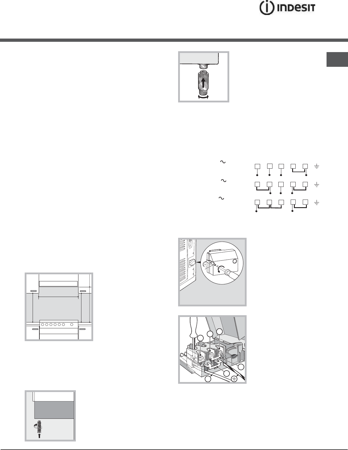
Electrical connections
Fitting the power supply cable
The cab le should be suited to the type of electric al
connec tion used, acc ording to the following
connection diagram:
To install the power supply cable correctly:
1. Loosen the screw V
in the terminal board
and p ull the cover to
open it (
see figure
).
2. Position the
connection support A
(
see figure
) acc ording
to the c onnection
diagram shown above.
The terminal board is
designed for single-
phase 230 V
connection: terminals 1,
2 and 3 are c onnec ted
to eac h other; jump er 4-
5 is loc ated in the lower area of the terminal b oard.
3. Position wires N and
88
88
8 accord ing to the diag ram
(
see fig ure
) and perform the connec tion by tig htening
the terminal board screws as much as possible.
4. Position the remaining wires on terminals 1-2-3
and tighten the screws.
Installation
HOOD
420
Min.
min.
650
mm. with hood
min.
700
mm. without hood
mm.
600
Min. mm.
420
Min. mm.
V
1
2
3
N
A
B
1 2
3
4
5
12345
1
2
3
4
5
R
S
T
N
R
S
N
R
N
400 3N
H05RR-F 5x2.5 CEI-UNEL 35363
400V 2N
H05RR-F 4x4 CEI-UNEL 35363
230V
H05RR-F 3x4 CEI-UNEL 35363
H05VV-F 3x4 CEI-UNEL 35746
H05VV-F 4x4 CEI-UNEL 35746
H05VV-F 5x2.5 CEI-UNEL 35746
15
Ваш отзыв будет первым